
Hybrid Topologies
Explain
- is a type of network topology that uses two or more other network topologies, including bus topology, mesh topology, ring topology, star topology, and tree topology.
Advantages & Disadvantages
Advantages of Hybrid Network Topology
1) Reliable : Unlike other networks, fault detection and troubleshooting is easy in this type of topology. The part in which fault is detected can be isolated from the rest of network and required corrective measures can be taken, WITHOUT affecting the functioning of rest of the network.
2) Scalable: Its easy to increase the size of network by adding new components, without disturbing existing architecture.
3) Flexible: Hybrid Network can be designed according to the requirements of the organization and by optimizing the available resources. Special care can be given to nodes where traffic is high as well as where chances of fault are high.
4) Effective: Hybrid topology is the combination of two or more topologies, so we can design it in such a way that strengths of constituent topologies are maximized while there weaknesses are neutralized. For example we saw Ring Topology has good data reliability (achieved by use of tokens) and Star topology has high tolerance capability (as each node is not directly connected to other but through central device), so these two can be used effectively in hybrid star-ring topology.
Disadvantages of Hybrid Topology
1) Complexity of Design: One of the biggest drawback of hybrid topology is its design. Its not easy to design this type of architecture and its a tough job for designers. Configuration and installation process needs to be very efficient.
2) Costly Hub: The hubs used to connect two distinct networks, are very expensive. These hubs are different from usual hubs as they need to be intelligent enough to work with different architectures and should be function even if a part of network is down.
3) Costly Infrastructure: As hybrid architectures are usually larger in scale, they require a lot of cables, cooling systems, sophisticate network devices, etc.
Types (Explain & Illustration)
Star Ring
A Star ring network consists of two or more star topologies connected using a multistation access unit (MAU) as a centralized hub.
Star Bus
A Star Bus (tree network) network consists of two or more star topologies connected using a bus trunk (the bus trunk serves as the network's backbone).
Snowflake
Snowflake topology is a star network of star networks
Backbone networks
Explain
A backbone is a part of computer network that interconnects various pieces of network, providing a path for the exchange of information between different LANs or subnetworks. A backbone can tie together diverse networks in the same building, in different buildings in a campus environment, or over wide areas.
Types (Explain & Illustration)
Serial Backbone
Serial backbone is formed of two or more devices that are connected in a daisy chain (linked series). It is a simplest kind of backbone. As the one can see from figure below, serial backbone can be made not only from switches, but also from gateways and routers.

Distributed Backbone
Distributed backbone uses hierarchical design of the network, where number of intermediate devices are connected to single or multiple connectivity devices. These central connectivity devices could be switches or routers and shown with purple color in diagram below.

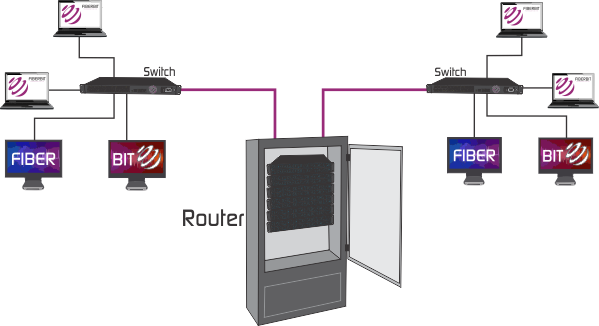
Collapsed backbone
This type of backbone uses single, powerful router as the central connection point for multiple subnetworks. As figure below shows, the central device is the highest level of the backbone. It should have powerful computational power in order to manage big traffic coming in. This is highly risky, since if the central device fails, the whole network would be down. However, this type of backbone is useful for the one who wants to interconnect two types of subnetworks, with ability to manage and troubleshoot them.
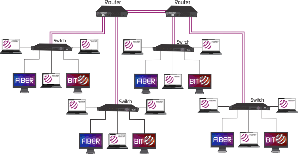
Parallel backbone
Parallel backbone is a variation of the collapsed backbone, where devices are having more than one connection between them. As diagram below shows, there are multiple connections between the high level routers and the network segments. Duplicate connections ensure networks availability at anytime, higher speeds, and high fault tolerance. Logical drawback of this solutions is the increased price, since amount of required cabling is highly increased. It is not obligatory to have duplicate connections between all the devices, selective implementation of parallel structure would significantly lower the overall price and make additional ports of the devices available.
Switching
Explain
The controlling or routing of signals in circuits to execute logical or arithmetic operations or to transmit data between specific points in a network. Note: Switching may be performed by electronic, optical, or electromechanical devices
Methods (Explain & Illustration)
Important Switching Methods are store and forward, cut-through and fragment-free. Switching Methods determine how a switch receives, processes, and forwards a Layer 2 Ethernet frame.

In Store and Forward switching, Switch copies each complete Ethernet frame into the switch memory and computes a Cyclic Redundancy Check (CRC) for errors. If a Cyclic Redundancy Check (CRC) error is found, the Ethernet frame is dropped and if there is no Cyclic Redundancy Check (CRC) error, the switch forwards the Ethernet frame to the destination device. Store and Forward switching can cause delay in switching since Cyclic Redundancy Check (CRC) is calculated for each Ethernet frame.

In cut-through switching, the switch copies into its memory only the destination MAC address (first 6 bytes of the frame) of the frame before making a switching decision. A switch operating in cut-through switching mode reduces delay because the switch starts to forward the Ethernet frame as soon as it reads the destination MAC address and determines the outgoing switch port. Problem related with cut-through switching is that the switch may forward bad frames.

Fragment-free (runtless switching) switching is an advanced form of cut-through switching. The switches operating in cut-through switching read only up to the destination MAC address field in the Ethernet frame before making a switching decision. The switches operating in fragment-free switching read at least 64 bytes of the Ethernet frame before switching it to avoid forwarding Ethernet runt frames (Ethernet frames smaller than 64 bytes).
http://www.ianswer4u.com/2012/05/hybrid-topology-advantages-and.html#axzz4A60gIMdr
http://info-it.net/Basic-Network/hybrid-topology.php
https://en.wikipedia.org/wiki/Tree_network
https://en.wikipedia.org/wiki/Network_topology#Hybrid
http://media.gettyimages.com/photos/data-networking-picture-id182160514
https://en.wikipedia.org/wiki/Backbone_network
http://fiberbit.com.tw/types-of-backbone-networks/
http://www.its.bldrdoc.gov/fs-1037/dir-035/_5214.htm
No comments:
Post a Comment