
Building Network
Screenshot of the Network

VLSM Table
Subnet the given
network with the following requirements:
192.168.10.0
- Building 1
·
IT 3 PCs
·
OFFICE 8 PCs
- Building 2
·
SALES 10 PCs
-ROUTER - TO - ROUTER
·
2 IPs
SALES – 10 PCs – (16 – 2 = 14) H4 S4 (128 + 64 + 32 + 16 = 240)
OFFICE – 8 PCs - (16 – 2 = 14) H4 S4 (128
+ 64 + 32 + 16 = 240)
IT – 3 PCs - (8 – 2 = 6) H3
S5 (128 + 64 + 32 + 16 + 8 =
248)
ROUTER TO ROUTER – 2 IPs - (4 – 2 = 2) H2 S6 (128 + 64 + 32 + 16 + 8 + 4 = 252)
Network Address
|
Host Range
|
Broadcast Address
|
Subnet Mask
|
I92.168.10.0
|
I92.168.10.1- I92.168.10.14
|
I92.168.10.15
|
255.255.255.240
|
I92.168.10.16
|
I92.168.10.17- I92.168.10.30
|
I92.168.10.31
|
255.255.255.240
|
I92.168.10.32
|
I92.168.10.33- I92.168.10.38
|
I92.168.10.39
|
255.255.255.248
|
I92.168.10.40
|
I92.168.10.41- I92.168.10.42
|
I92.168.10.43
|
255.255.255.252
|
I92.168.10.44
|
ROUTER, NETWORK, VLAN Table
Device
|
Interface
|
IP Address
|
Subnet Mask
|
Default Gateway
|
Sales
|
Vlan
1
|
192.168.10.14
|
255.255.255.240
|
192.168.10.1
|
PC
1
|
NIC
|
192.168.10.3
|
255.255.255.240
|
192.168.10.1
|
PC
2
|
NIC
|
192.168.10.4
|
255.255.255.240
|
192.168.10.1
|
PC
3
|
NIC
|
192.168.10.5
|
255.255.255.240
|
192.168.10.1
|
PC
4
|
NIC
|
192.168.10.6
|
255.255.255.240
|
192.168.10.1
|
PC
5
|
NIC
|
192.168.10.7
|
255.255.255.240
|
192.168.10.1
|
PC
6
|
NIC
|
192.168.10.8
|
255.255.255.240
|
192.168.10.1
|
PC
7
|
NIC
|
192.168.10.9
|
255.255.255.240
|
192.168.10.1
|
PC
8
|
NIC
|
192.168.10.10
|
255.255.255.240
|
192.168.10.1
|
PC
9
|
NIC
|
192.168.10.11
|
255.255.255.240
|
192.168.10.1
|
PC
10
|
NIC
|
192.168.10.12
|
255.255.255.240
|
192.168.10.1
|
IT
|
Vlan
1
|
192.168.10.38
|
255.255.255.248
|
192.168.10.33
|
PC
1
|
NIC
|
192.168.10.34
|
255.255.255.248
|
192.168.10.33
|
PC
2
|
NIC
|
192.168.10.35
|
255.255.255.248
|
192.168.10.33
|
PC
3
|
NIC
|
192.168.10.36
|
255.255.255.248
|
192.168.10.33
|
Office
|
Vlan
1
|
192.168.10.30
|
255.255.255.240
|
192.168.10.17
|
PC
1
|
NIC
|
192.168.10.18
|
255.255.255.240
|
192.168.10.17
|
PC
2
|
NIC
|
192.168.10.19
|
255.255.255.240
|
192.168.10.17
|
PC
3
|
NIC
|
192.168.10.20
|
255.255.255.240
|
192.168.10.17
|
PC
4
|
NIC
|
192.168.10.21
|
255.255.255.240
|
192.168.10.17
|
PC
5
|
NIC
|
192.168.10.22
|
255.255.255.240
|
192.168.10.17
|
PC
6
|
NIC
|
192.168.10.23
|
255.255.255.240
|
192.168.10.17
|
PC
7
|
NIC
|
192.168.10.24
|
255.255.255.240
|
192.168.10.17
|
PC
8
|
NIC
|
192.168.10.25
|
255.255.255.240
|
192.168.10.17
|
Building 1
|
||||
IT
|
Fa0/0
|
192.168.10.33
| 255.255.255.248 | |
Office
|
Fa1/0
|
192.168.10.17
|
255.255.255.240
|
|
Se2/0
|
192.168.10.41
|
255.255.255.252
|
||
Building 2
|
||||
Sales
|
Fa0/0
|
192.168.10.1
|
255.255.255.240
|
|
Se2/0
|
192.168.10.42
|
255.255.255.252
|
The default gateway of the PCs is the first valid host range.
For the router. the IP address of the fastethernet (fa0/0) is the default
gateway of the switch.
IP ROUTE Table
Network Name
|
Network Address
|
Subnet Mask
|
First HOP
|
Building 1
|
|||
Sales
|
192.168.10.0
|
255.255.255.240
|
192.168.10.42
|
Building 2
|
|||
Office
|
192.168.10.16
|
255.255.255.240
|
192.168.10.41
|
IT
|
192.168.10.32
|
255.255.255.248
|
192.168.10.41
|
For the first hop for building 1, get the serial address of building 2 and vice versa. and then get the IP address of other router.
Date : 22/06/2016
Basic Configuration of Router R1
BUILDING 1


BUILDING 2


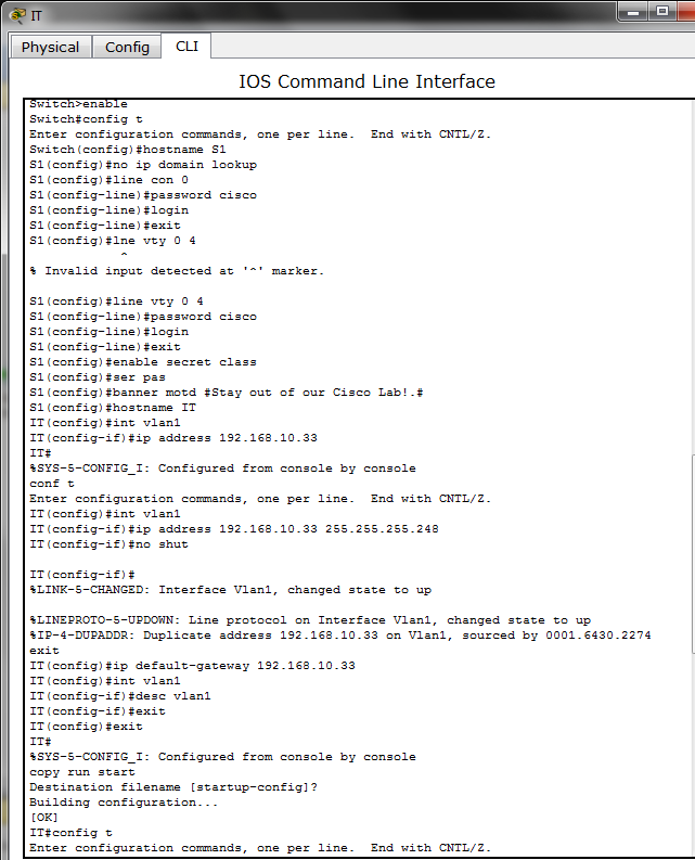
IT config

OFFICE config

SALES config

Ping:
1. Building 1 Router - Building 2 Router

2. Any Office PC - Building 1

3. Any IT PC - Any Office PC

4. Sales Switch - Building 2 Router

Telnet
1. Any Sales PC - Office Switch

2.Building 1 Router - Sales Switch

No comments:
Post a Comment